
Traffic Light Tracking
March '18
Traffic Light Tracking
March '18
Computer Vision
March 2018
Background
LiDAR- what it is, why it is relevant
Reference Velodyne LiDAR page
Remote Sensing- class at UMD, build our own LiDAR systems to map something on campus --> note less design, more build

Medical Robot: Phase 2
November - December 2017
Background
This was the final phase of a project for a course in Medical Robotics taken during the Fall Semester of my senior year. I worked in a group with two other engineering students.
Using three linear robots, this project was designed to move in the X-Y-Z directions and puncture three targets (yellow) with a needle based on image recognition from a webcam.
Once again, all the material was supplied, but with limited assembly instructions-- leaving the door open for some guess work [...and debugging].

Targets
Fiducial Reference Frame

Stepper motors
Webcam
In order to properly find the targets with the webcam, a fiducial reference frame was established (blue). The X-Y-Z positions of the targets were given in the fiducial reference frame.
Therefore, with image recognition, we could detect the positions of the fiducial markers and find the targets based on those.
Build Process
The robot was built using most of the material from the three linear stages along with a rack and pinion to move the needle.
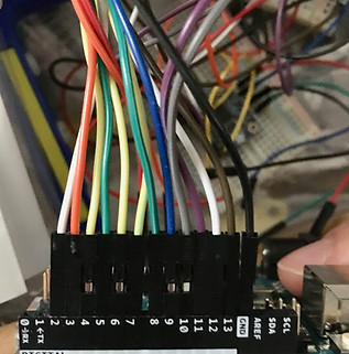
Assembly was rather straightforward and didn't require any additional machining. It did, however, require complicated wiring as the three motor drivers were all wired to the same Arduino.

Testing
This was by far the most extensive and time consuming part of the project [it took us 20 hours to get it right]. To start, none of us had experience running the Webcam Support Package in Matlab, which was crucial for finding the targets.
First, the webcam had to be calibrated in Matlab. Using a checkerboard grid, I was able to extract the grid corners of each checker box. This established a pixel coordinate frame for the camera.
[Admittedly this was pretty cool-- based on 20 pictures by a webcam, Matlab could determine the real world distance between points in all pictures taken by that webcam.]


In order to better detect the fiducial markers [key for finding the targets], we inserted LEDs into the marker holes. Matlab could better identify these locations in the webcam picture based on color, eccentricity, and light intensity. This drastically improved the accuracy and consistency at which the markers were found.
The Matlab code then took these pixel locations and converted them to distances for the robot to move [using fancy matrix manipulation combined with set measurements].
Side note: we used a white background during testing to help pick up the fiducials better. We ended up not needing it during the demo.
Finally, Matlab would call the Arduino command to move the stepper motors in the X-Y-Z directions [using the number of steps per revolution found in Phase 1].
Overall, our robot was painfully precise. We did extensive testing prior to demoing the project in class and had amazing results-- hitting all three holes consistently [even the smallest one]. The robot would still hit the targets even when they were moved in the X and Y directions.
Demo


Lessons Learned
This project really demonstrated the power of Matlab. I learned how to utilize Matlab extensions/toolboxes to interface with a webcam. I also picked up on a bunch of Matlab tricks from my group members throughout the testing process.
On the topic of group members, I worked with an great pair of intelligent individuals that made a seemingly overwhelming project doable-- even if it meant walking through the code for the millionth time at three in the morning.
Though unexpected, this project called for a bit of creativity to ensure that the fiducial markers were always detected in the webcam photos [cue LED idea]. This was a painful trial and error process that taught me the importance of thinking outside the box especially when you're stuck.
Lastly, our robot could not return to the "home" or reset position [though we programmed it to do so]. We concluded it had to do with the power draw of the stepper motors, particularly the one lifting the rack and pinion in the Y-direction. Due to the weight of this portion of the robot, the stepper motor encountered more resistance than the power supplied. This reminded me to consider the materials and actuation needed to move those materials.